Detroit, MI -- It just amazes me how a good header fabricator can twist, loop, and thread large diameter steel tubing through the cramped and confined space of an engine compartment - especially a factory frame rail engine compartment. Performance Welding's Curt Zaske is considered an expert in the world of tubular fabrication. He has a ton of experience working many years as fabricator who has been building headers for 12 of those years. He's built headers for everything from 'Cup & Grand National cars, to Drag Cars, Desert Trucks, Custom Cars, and even several special OEM projects.
Curt put a lot of time in upfront to assure that this project would go as smoothly as possible. The guy was constantly on our phone planning, checking, and double-checking everything - almost to the point of over analyzing the project. But that's good! That's exactly the way we like it and would turn out to be exactly what we'd need as the project progressed.
The first thing Curt had us do was consult with his preferred exhaust system material supply company to determine the best dimensions for our high-revving nitrous application. After filling out an engine specification sheet and discussing some of the sheet's finer details, the simulations suggested that we go with a three-step primary tube, 25" in length, using a merge collector with a 4 ˝" outlet. These numbers were very close to what our tuner, Jeff Prock of Applied Nitrous Technology, had suggested weeks earlier so this part of the program was easy. What wouldn't be so easy is figuring out how to build those numbers into a set of headers for our car.
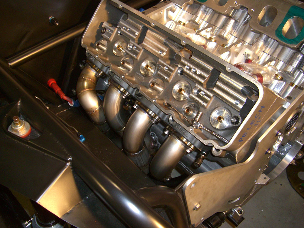
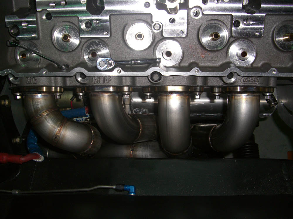
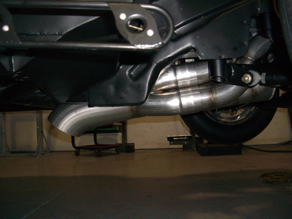
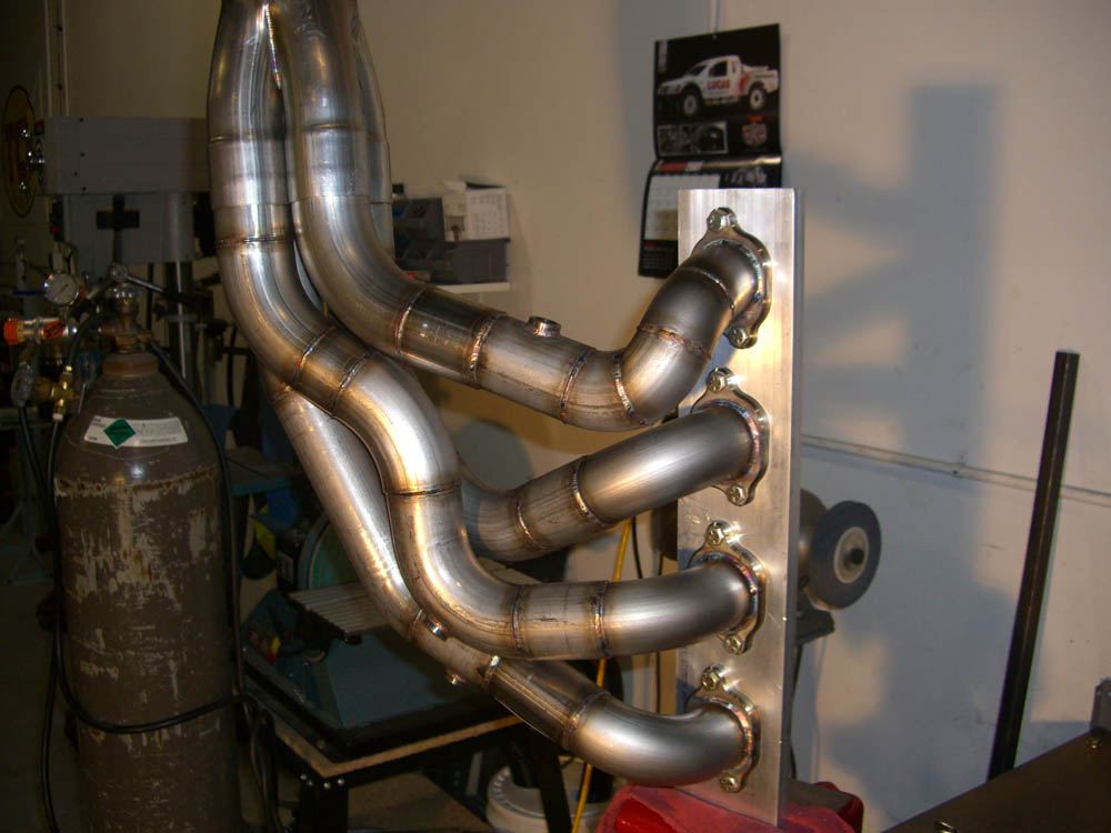
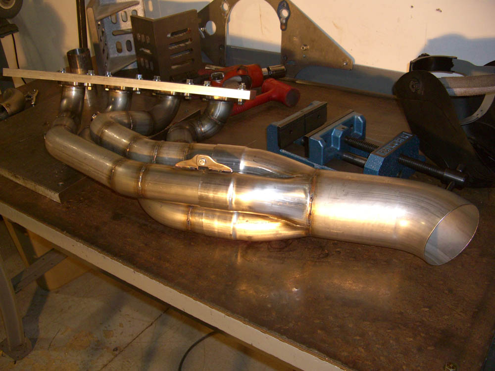
One day after out the stainless steel materials arrived, I was shocked to get a call from Curt saying that he had the whole right bank of headers tacked together and ready for us to check out. You heard me right… The guy did one whole side in one night! It get's crazier… The configuration he showed us was actually the third iteration of the night. Those big tubes made for a really challenging install that required a few routings before the best compromise was determined. And don't think for second that the quick work was shoddy. When Tim and I inspected, it was clear that this was a well thought out and executed plan. Curt uses special drawing templates and blocks to assure that each cut is perfect perpendicular to the center line of the U-bend, assuring a smooth and uninterrupted flow. With a couple minor tweaks to the primary tubes for cylinder 6 & 8, Curt was ready to finish weld the 'even-side' together. The only other issue that needed to be addressed was the collector configuration. Originally, a 4 ˝" diameter straight outlet was specified for our application. But… Our front frame rail basically forced the outlet to be pointed treacherously close to the transmission and I'm about certain that racing transmission builder extraordinaire, John Hutchinson of Hutch's Transmission Service wouldn't look kindly upon us blowing a three-foot blue flame down the side of his transmission. Outside of significantly cutting on the chassis, the only choice was to use a 'turn-down' style collector outlet pipe. It wasn't what we had hoped for but it was the best alternative for our dilemma.
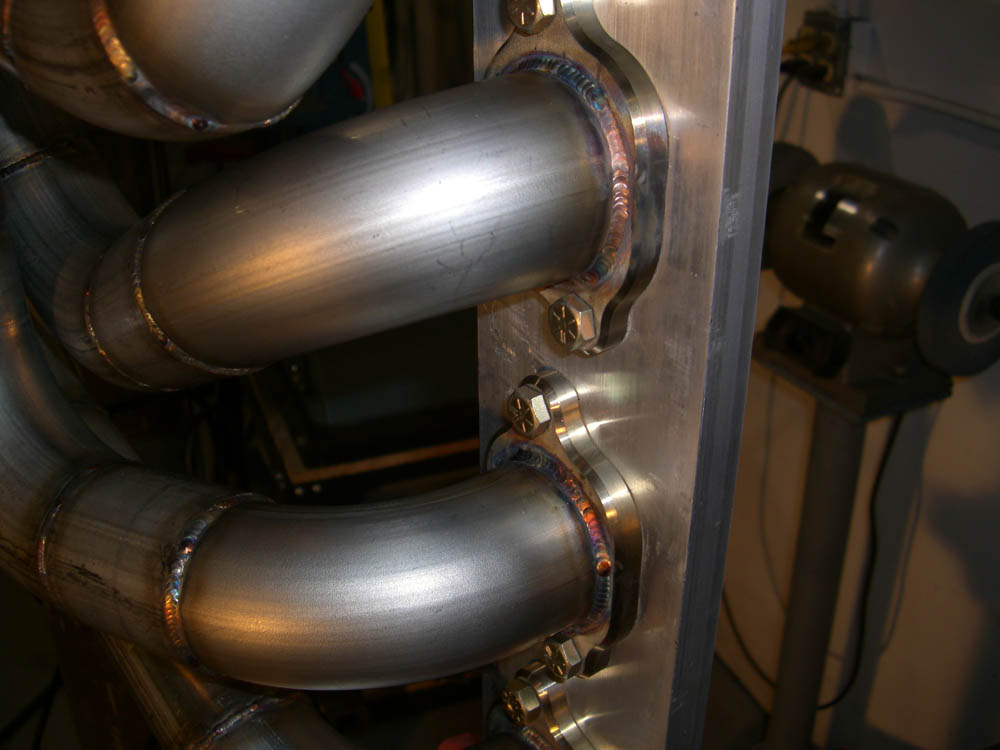
Curt's next step is bolting the tacked together header assembly to a fixture plate that represents the exhaust face of our cylinder head. What comes next is pretty interesting; He attaches a rubber boot and air hose to the end of the headers that back fills the pipes with Argon shielding gas. This process is called 'Purging' and it insures the best possible environment for welding on stainless steel. I asked Curt why this was important. "On thin wall material, there are two side to a good weld and it's just as important to provide shielding gas to the opposite side of the weld as it is the side that you're actually welding on. This keeps you from contaminating the weld from the inside of the tube." Curt said. He then added, "This is important with stainless steel because you can get what we call "Sugaring" on the inside of the tube. The weld will actually deteriorate and expand on the inside of the tube, reducing the cross sectional area of the pipe at each weld. You can think of it as a speed bump on the inside of the tube at every weld. It's easy to have 6 or more welds per tube and that all adds up to a lot of unnecessary impediment of the exhaust flow and, depending on fuel type, temperature & pressure, can eventually lead to failure at the weld. When people spend as much money as they do on stainless steel headers, that's the last thing they want to hear about."
The other concern Curt noted was excess heat in the weld. With thin wall stainless steel, Curt says you really can't weld much more then 1 ˝" at a time without affecting the integrity of the weld. Ideally, a weld on stainless steel will be a gold & purple rainbow color. If the weld turned gray, it means it got too hot. That's why it's important to jump around, and not continuously weld in one area, to prevent building up too much heat. Excess heat also greatly contributes to the 'Sugaring-Effect' Curt mentioned earlier.
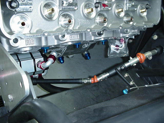
The driver side headers wouldn't go quite as easily as the opposite side. Simply put, there is just too much crap in the way. Steering shafts, dry sump oil pump, spark plugs, external water lines, oil pan pick ups & hoses fought Curt every step of the way. The Pro Stock-style block we use with it's super-short deck and the unique exhaust face of our cylinder head didn't help the situation as you think it would. The block's short deck helped provide space by pulling the heads closer together, way form the frame rail, then they would be on a taller deck block. But the exhaust face of the cylinder head we use is rotated somewhat upward pointing the exhaust port straight at our frame rail. In short, the natural direction of the exhaust port is out, instead of down, killing any header space we would've gained (and then some) with the short deck. Even though the passenger side only took Curt a day, he toiled over the driver's side for nearly a week, and through a dozen different routings before coming up with the best possible compromise for a 'no-win' situation. Curt literally exhausted all options for these four tubes.
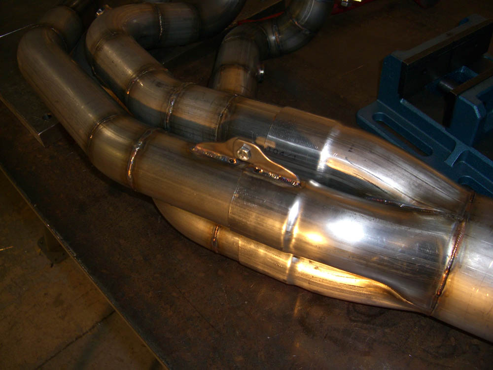
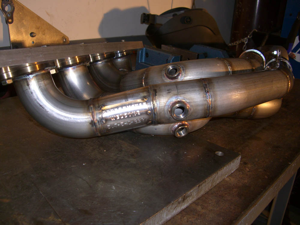
After finishing the collector treatments, Curt moved on to placing the O2 sensors bungs. As you can see, we'll be running eight O2 sensors - at all times - to best utilize the individual cylinder tunability of our F.A.S.T. electronic fuel injection system. Prock has done quite a bit of work with eight O2 sensor systems and has been amazed at the un-ending wealth of data that has come from them. The 'Cliff Notes' version is, with an O2 sensor in every tube, you can quantify and optimize the exact efficiency of each individual cylinder for maximum output. Now, each cylinder will literally be it's own optimized sub-system attached to a common crankshaft.
Prock specified that each bung was to be positioned approximately 12" downstream of the exhaust flange to assure the best signal for the O2 reading and to prevent inaccurate readings due to overlap.
The photos you see at the right are the result of Curt's expertise and dozens of hours of labor. The photos really don't do the headers any justice or convey the difficulty that our car created during the build process. You'll just need to check them out on our car for yourself to appreciate it. Through it all, Curt kept us informed of every development, worked quickly to over come any challenges that were presented, and beat the tight deadline that we all agreed to beforehand. You've got to be impressed by a guy who can create what you see on the right in less then 40 man hours.
Thanks, Curt…
Ted & Tim Pelech
Pelech Bros. Racing
www.PelechBrosRacing.com