Detroit, MI -- Our website always seems to generate a lot of interest when we delve into some of the more technical aspects of our racecar. If you're one of those who love to get a closer look at 'how it's done', we've got a treat for you. John Marcella of ET Performance is going to guide us through a step-by-step pictorial of the building of a hand fabricated sheet metal intake manifold.
The amount of planning & design that goes into one of these aluminum marvels is tremendous. Just as hours upon hours can go into developing the perfect cylinder ports, the same, and then some, can be said for an intake manifold. Now consider, just for a minute, all of the things that take place within the confines of an electronic fuel & multi-stage nitrous oxide injected intake manifold. We've got air, gasoline, and nitrous oxide all violently intermixing with each other within the blizzard that is a multi-stage nitrous oxide injection system. Some how, through all of that frozen chaos, the air, fuel, and nitrous-oxide must remain a homogenous mixture and actually make it all the way down the port, past the valve, and into the cylinder without losing the fuel on the port walls along the way. That's where experts like John Marcella and Jeff Prock of Applied Nitrous Technology come in.
John began the design process by drawing the ideal intake manifold for our engine combination. Afterward, Jeff reviewed the drawing and specified the necessary provisions to accommodate the cutting edge fuel & nitrous delivery that he has designed just for this occasion. After the happy median was established and raw materials were in hand, John donned his welding helmet and went to work fabricating according to his drawing.
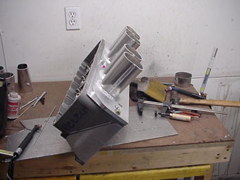
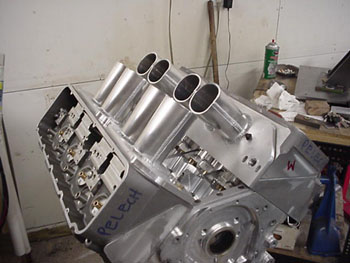
John begins buy forming the top and bottom halves of each runner around a specially machined die that he attaches to a your typical sheet metal brake. The aluminum stock is clamped into the brake and then rolled around the die. After that, he trims the halves to his ideal runner shape and then welds them together. The flange end of the welded runner is trimmed to size before it's welded to the flange face. That process is repeated three more times to complete a single bank of four of runners. John then repeats the entire process again for the opposite bank.
In a few days, we'll upload the next step; fitting the plenum. So be sure to check back soon and thanks for stopping by!
Ted & Tim Pelech
Pelech Bros. Racing